Digital Beamsteering Phased Array

Team 311
Tiernen Pan
Software Lead
Tiernen is an Electrical Engineering student planned to graduate this upcoming May 2022. As the software lead, Tiernen's main focus is using the VHDL to implement the beamsteering equation into the FPGA. Tiernen also uses VHDL to implement the user interface which allows the user to steer the beam. Additionally, Tiernen works closely with the team's assisting advisor to ensure our VHDL code is properly implemented.

Christian Balos
Signal Integrator
Christian is an Electrical Engineering student planned to graduate this upcoming May 2022. As the signal integrator, Christian focuses on the propagation of signals. Christian assists William in designing the PCB by making sure each component's input can support the output of the previous component. Additionally, Christian helps assist Tiernen in designing the VHDL software.
William Snyder
PCB Designer
William is an Electrical Engineering student planned to graduate this upcoming May 2022. As the PCB Designer, William is in charge of the printed circuit board. He must locate the footprints and symbols for each component required PCB component. William works closely with Christian to ensure the propagation of signals between each component is properly integrated. Additionally, William works closely with assisting professors who review our PCB design.

Katheryn Potemken
Antenna Lead
Katheryn is an Electrical Engineering student planned to graduate this upcoming May 2022. As the antenna lead, Katheryn leads antenna testing and assists William in designing the antenna portion of the PCB. In addition, she is also the financial advisor for the team and sends out the parts order to the school. Furthermore, Katheryn also keeps the team organized in coordinating meetings and balancing project progress.

Andrew Cayson
Hardware Assembler
Andrew is an Electrical Engineering student planned to graduate this upcoming May 2022. As the hardware assembler, Andrew takes the lead when it comes to assembling the prototype and final design. This will include soldering and connecting the various subsystems through specialized high-frequency cables. Additionally, Andrew works closely with the DDS by testing it to ensure it is generating given signals correctly.
Project Abstract
A technique called beamsteering is the process of rotating the direction of the signal through a series of signal delays. This changes the radiation direction without physically moving the transmitting antennas. The market for beamsteering antenna arrays is extremely vast and can be used across multiple industries. For military applications, it is useful for improving the speed and range of radar systems. For civilian applications, it can be useful in communication systems, allowing for the technological progression of 5G systems and satellite to ground communications.
This project aims to develop a setup that allows the ease of implementation of beamsteering. It is software-based and uses digital techniques for flexibility. The setup contains commercially available parts, such as the four transmitting antennas, to reduce the cost of the system. The system will be controlled through the FPGA development board, which is essentially the brain of the project. The setup supports a high-intensity signal of 2.4 GHz and has the ability to transmit the signal in any given direction with a range comparable to an average household router. This project tasks the team with creating a transmitting antenna array, which is multiple antennas arranged in a line, to implement beamsteering. When thoroughly reviewing the datasheets, the team studies the propagation of the input/output signals for each component and how it connects to one another for hardware assembly. After confirming these I/O ports, the team can write the software necessary for the project. The goal of the software design is to create an unmodified signal and control the direction the signal is transmitting. This project transmits a focused high-intensity signal that can change the radiation direction. When testing the final project, the team will use the assisting professor's antenna lab to check if the signal was properly transmitted. Overall, this project aims to develop a setup that allows beamsteering implementations.Project Status
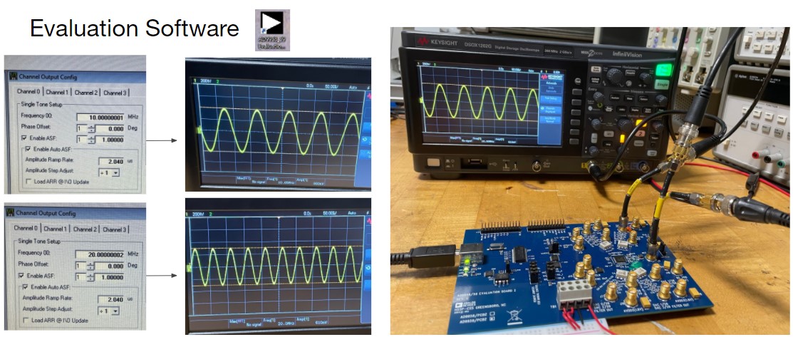
After sending the PCB design out for fabrication, the team could then focus on testing DDS. This ensures that there is a signal being properly transmitted.
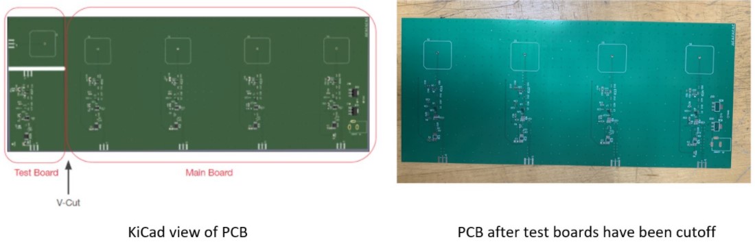
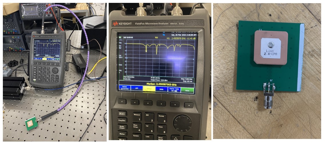
Once the PCB arrived, the team first had to get the PCB test cutouts separated from the rest of the board.
Once the test cutouts are separated, the team first tested the antenna. The quality of the soldering job plays a large role in the efficiency of the antenna. After testing two different antennas with two different solder jobs, we chose to interpret the data of better soldering job because it gave us better results.
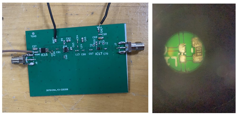
The team next tested the PCB cutout with all other components. This was great soldering practice, for the team has never soldered components this small.
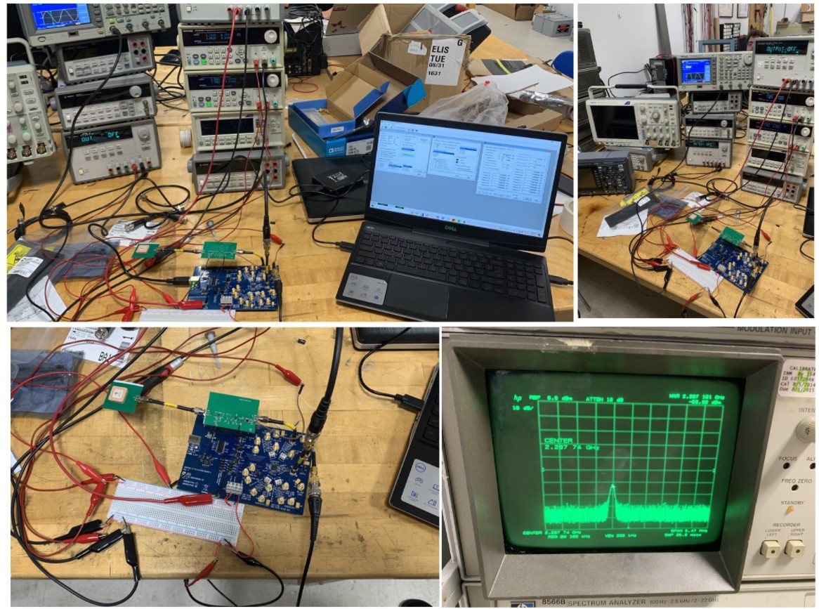
After successfully soldering all components on to the PCB test cutout, the team was able to test this cutout. The cutout was connected to the breadboard through the wires soldered to the board. The breadboard allowed for the team to hook up multiple power supplies to power the system. There were also power supplies powering the DDS as well. A laptop was connected to the DDS to control the DDS. We then connected the output of this setup to an oscilloscope. Here the team was able to see an amplified signal of 2.287 GHz. This was very successful testing for the team is not far off from reaching their required frequency of 2.4 GHz.
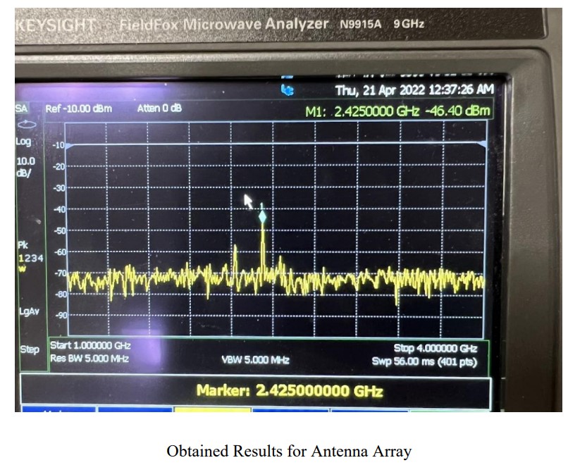
The team next tested the test cutouts at a channel to make sure it is properly transmitting the 2.4 GHz signal. The single channel was indeed transmitting a 2.4 GHz signal at around -42 dBm.
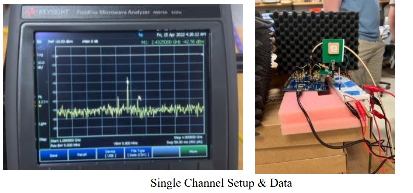
The team next tests the final design. Here you can see the setup of the final design.
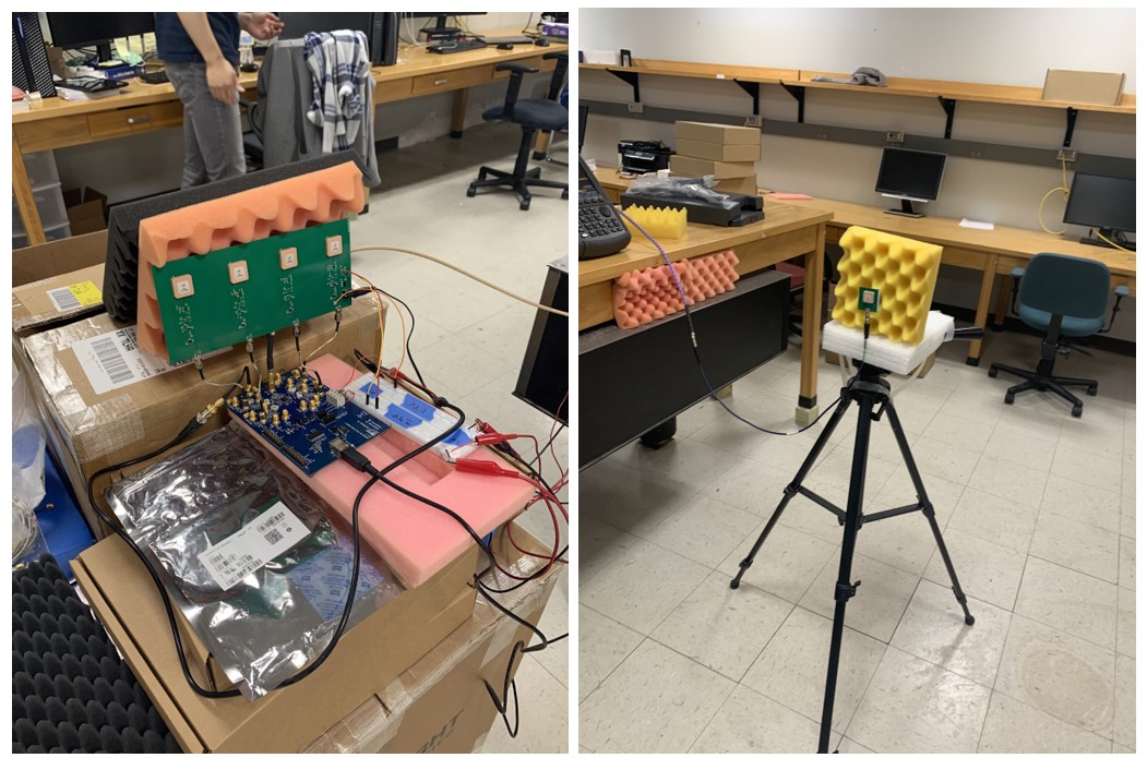
Only two of the four channels were operational. This was enough to perform beamsteering, but the beam was not able to be steered because the device had not been calibrated due to time constraints. The receiving antenna was not directly in front of the transmitting antenna array when the phase offset for all the antennas were set to zero, meaning that at least two antennas were operational, but were not properly calibrated. Here you can see the final results for the antenna array.
Overall, the team has learned a great amount about RF throughout this experience. The team started with minimal knowledge on the subject of RF, PCB design and designing a circuit using commercial parts such as the voltage-controlled oscillator, amplifier and mixer. For the first time, the team had to make practical choices based on specification sheets and this would not have been possible without the help of Dr. Arigong and PHD students. However, throughout the design and overcoming a lack of knowledge, we were able to deliver a successful circuit that upconverted from 200 MHz to 2.4 GHz and had a strong signal of 3 dBm. The four-channel array, which would be the final product, would have been successful if the team had more time and experience on soldering. There were many lessons learned, especially on the PCB side, such as the need for more testing. One such play would be an SMA connector before it went into the antenna, as well as a switch to act as a breaker so that the team could test each individual channel. On the soldering side, it would have simplified the soldering experience massively had we ordered a PCB stencil with the PCB board. On the software side, we also learned that it would have been much easier to use SPI to feed the DDS values using a MCU instead of the FPGA, which we attempted for the majority of the year. This project was definitely a learning experience and served as a brief peek into the life of an engineer.