|
Component 3: The Solar Collector
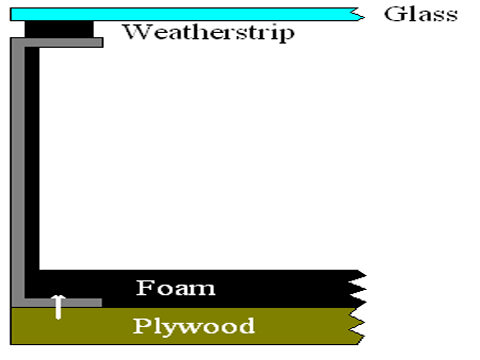
The solar collector was the most radical part of the design. A large box without a lid and bottom was constructed of steel stud u-channels. This box was fastened to a piece of plywood to keep it rigid. A large sheet of foam insulation was placed within the box on top of the plywood to insulated the bottom. One half inch thigh sheets of styrofoam were put in the u-channel of the box to insulate the sides. Weather stripping was placed all around the top of the box and a sheet of glass was laid on top. The joint between the plywood and the steel stud was filled with "Great Stuff" to prevent leakage of air. Below is a diagram of the system.
 
Solar Collector Construction
In order to have the air distributed evenly through the collector, a nozzle and diffuser was constructed. The diffuser is composed of 5 channels and is placed at the inlet of the solar collector. The nozzle is a wide V shape that brings all the air back to the exit barb and is placed at the exit of the collector. The solar collector was tapped and fitted with a 3/8" barb on each of the short ends so that it could be integrated into the whole system. Below are pictures of the completed solar collector.
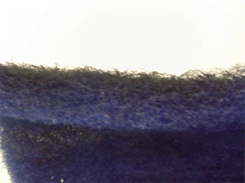
The transfer medium chosen was fiberglass filters. The filters were originally blue but the top was painted black to increase heat absorbotion. The transfer medium was then laid in the collector and attached to wood guides cut into triangles with a 5 degree angle of inclination. The transfer medium can be seen below.
 
Fiberglass Transfer Medium
|

