 |
The
coil leads were split and extended so slip-rings could be connected to the
coil in parallel (figure XX, left). |
 |
The
wires were fed through the appropriate radial holes out to the large hollow
end of the shaft (figure XX, center |
 |
The
coil was carefully pushed into the shaft and aligned with its mounting
holes. The mounting screws were tightened to secure the coil
tangentially to the inside of the shaft wall (figure XX, right). |
 |
Next,
the shaft was mounted in the bearings (figure XXI). The AC4598
slip-ring had to be mounted first because it lies in between the two
bearings. It was not, however, secured to its base yet. Instead,
the wires were taped securely to the shaft to prevent the slip-ring stator
and rotor from rotating relative to one another.
The encoder was mounted and secured to the shaft. The
CAY-731 and SM-050 slip ring rotors were also tightened to the shaft. Their
stators were not yet mounted, to prevent premature wear of the brush/ring
contacts.
The
motor was mounted to the 8020 frame and aligned with the shaft. Alignment
was accomplished using levels, straight-edges, squares, and visual
observation.
|
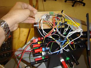 |
The
electronic circuits (figure XXII, left) and wiring box were fabricated
(figure XXII, right). |
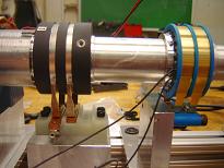 |
After alignment and initial testing, the CAY-731
and SM-050 stators were attached to their respective rotors (figure XXIII).
The stators hold the delicate brushes that contact the rotating rings of the
slip-rings. |
| |
Finally, the components were wired appropriately,
according to table II.
|