[ Operations Manual ]
Boeing: Electromagnet Actuator
Design
Method
1. Problem Identification
NEED: The
customer’s need for this project consists of a design concept that will allow
power to be transmitted through a bearing.
Objective and Goals:
·
To continue and create a working model for the Boeing: Power Switching Thrust
Bearing project started during the fall of last year.
· To provide the working prototype for an electromagnetic actuator that can transverse a given distance and provide a given load.
· Fully understand all numerical analysis and theory behind the original project design and use all available information to modify and optimize the product.
·
The team must correct the flaws of the original design and completely redesign
the actuator to create a functional project design.
· Product must be able to operate under determined thrust loads.
· Design must also be able to withstand a high shock load.
· Design must be fully functional in all respects and prove reliable results over a multitude of tests.
· Design has to be manufactured in the allotted budget.
Criteria for evaluating design
· Magnet design is all that would need to be completed because entire apparatus is complete.
· Use a Direct Actuation Redesign. Use Universal Actuators with an adapter.
·
Universal design that can easily adapt to different situations.
·
The power source and adapters are below the system and most of the stress would
affect the bottom of the system where maintenance access is the easiest.
2.
Conceptualization
· The design has the least pieces, it is the cheapest, easiest to build and least likely to fail.
· The design is universal and will work for all different sizes and applications.
·
It is over twenty times more powerful than last years design for less
than twenty percent the price.
·
Motor will receive power from outlet.
·
The customer likes it.
3. Synthesis
a Components
1. Housing
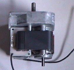
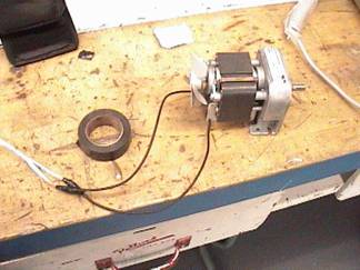
2. Motor
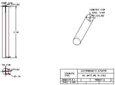
3. Shaft
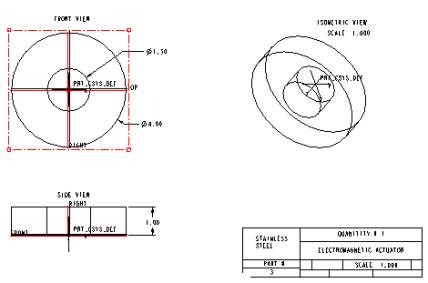
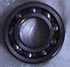
4. Ball bearing
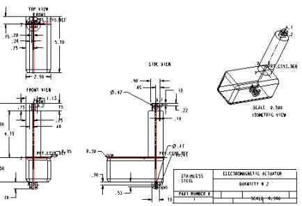
5. 2 Actuators
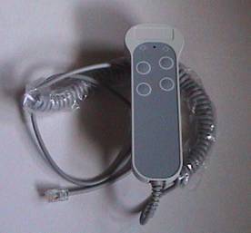
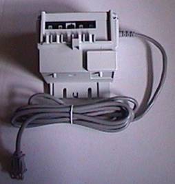
6. Control Box w/ switches
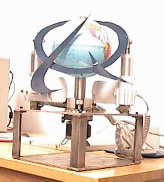
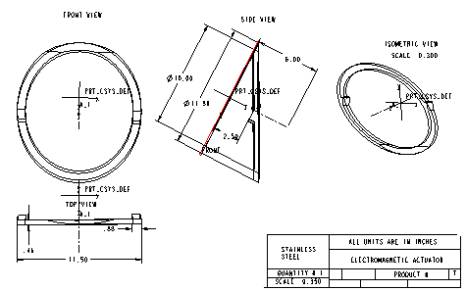
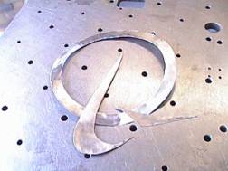
7. The Halo
b. Dimensions and Schematic Design of Components
1.
The Bearing.
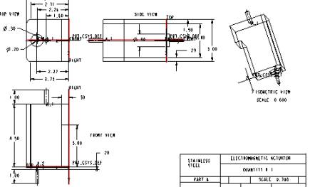
2. The Actuators
3.
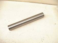
The Shaft
4. The Halo
5.
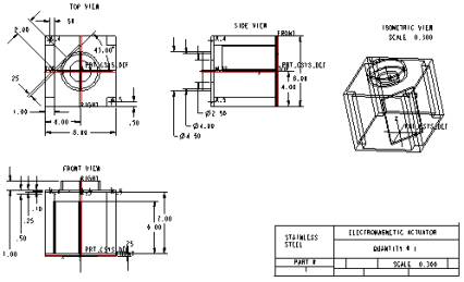
The Housing
6.
The Motor
4. Analysis
a Theoretical Analysis
1. Force Analysis
2. Heat lost due to surface area
3. Cost to manufacture design
b Testing
1. Function and output of motor
2. The required load to operate to
3. Test all assumptions
4. Test whether it work or not
5. High Shock loads
5. Manufacturing
If the simple calculations are calculated and measured
correctly and the assumptions are right, the design should be a success.
The amount it would cost to design this product should be cheaper than
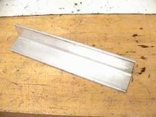
the previous design. The housing is
going to be made of stainless steel (type 403). This material is sturdy and
would be able to withstand any and all forces from the actuators and the
rotating shaft. To achieve the performance specifications a suitable bearing was
chosen that would resist an axial of the weight of the shaft and a radial load
from 100rpm. A ball bearing that met the required bore and thickness was
selected. Taking into consideration
a reasonably budget of only a few thousand dollars, the system was designed to
lift with a force of 2700lb and the central shaft will spin at 100 rpm.
These specs are still lower than the original request of 3000lb force and
10,000rpm, but are the highest that will occur if staying in the price range of
a couple thousand dollars. To
attain rotation in the system an AC electric motor will be inserted at the base
of the shaft. The electric motor
should have a torque that will be able to rotate the weight of the central shaft
as well as any friction between the shaft and the bearing.
Thanks
For Taking The Time To Review The Electromagnet
Actuator
Redesign (Direct Actuation)!
We’re glad you are looking at the design of the Direct
Actuation. Everything we know about
actuators, switches, magnets, steel, mechanical engineering, and different
conceptual aspects, went into the design and construction of this complete,
high-tech Direct Actuation System.
The design is well made, and carefully put together step by
step. We also stand behind it with
a knowledgeable, dedicated company (Boeing), so should you ever have any
questions or problems, you’ll receive fast, considerate assistance.
Thanks again, from all of us
Jerrell Houston
June Hutchinson
Nick Trupia
Donnell Smith
Students at FAMU-FSU College of Engineering (Mechanical Department)
IMPORTANT
SAFETY INSTRUCTIONS
When using an electrical appliance, basic precautions should be observed, including the following:
READ ALL INSTRUCTIONS BEFORE OPERATING THE TEST
APPARATUS.
WARNING: To reduce the risk of fire, electric shock, or injury:
· Do not leave design unattended when the motor is plugged in.
· To eliminate risk of shock operate only in a dry and well-ventilated area.
· Do not allow children to operate design or use as a toy.
· Close attention is necessary when used by or near children.
· Do not use with damaged cord or plug.
· Use only manufacturer’s recommended parts.
· Do not operate with wet hands.
· Turn off all controls on control box and motor before plugging any part of the design in.
· Keep on a level surface.
· Do not try to pick up the design while in use.
· Handle bearing with care due to it fragileness.
· Do not use for any purpose other than described in this User’s Guide.
List
of Parts for Design
Part #1.1:
Control Switches for Actuators
Part #1.2: Bearing
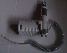
Part #1.3:
Motor
Part #1.4: The Control Box
Part #1.5: 2 Actuators
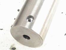
Part #1.6 The Shaft
How to Use This Guide
This User’s Guide has been designed to help you get the most satisfaction and understanding from the design. You’ll find assembly and operating instructions, safety precautions, as well as maintenance and troubleshooting instructions. Please read this Guide thoroughly before assembling and operating the Electromagnet Actuator Redesign (Direct Actuation).
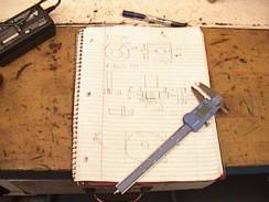
Pay particular attention to the design diagram, assembly instructions, and part names. Locate and organize all parts before assembly. Familiarize yourself with the parts and where they fit. Following this user’s Guide will greatly enhance you ability to get the most performance from the Direct Actuation.
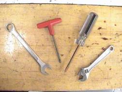
Some of the tools needed will in a wrench, screwdriver,
adjustable wrench, and an alley wrench.
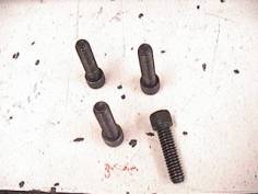
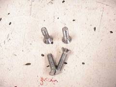
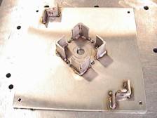
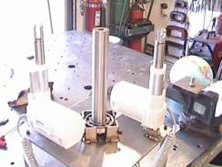
a. Weld the four 6in columns in the corners of the 12x12 stainless steel plate
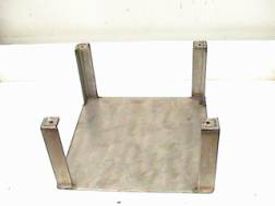
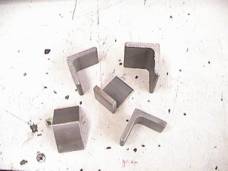
2. Drill and counter tap 4 5/8 holes in the 2nd 12x12 plate corners and 4 in middle as shown. In middle of plate drill and tap ¾ hole for motor. Weld the actuator mounting brackets as seen.
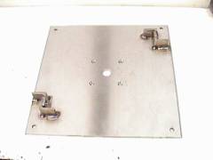
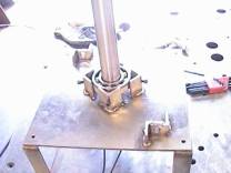
3. Place 2nd plate with the actuator-mounting tap on the other end of support columns and screw the screws in the mounting plate to the support columns.
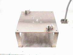
4. Weld four support columns in middle of plate as shown below.

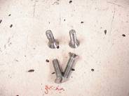
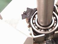
6. (a) Hydraulically press bearing on shaft, and place shaft on top of motor shaft and place set screw in side of shaft to screw shaft to motor, and (b) place support screws in side of support columns to bearing.
a. b.
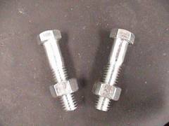
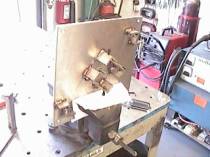
7. Now place actuators on the 2 corners diagonal to each other on actuator’s bracket and place the 2 screws and nut to tighten up the actuators.

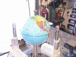
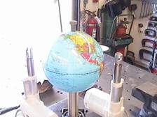
8.
Now place globe on top of shaft and bolt it down.
9.
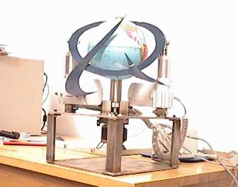 |
10. Last plug actuator and control switches into control box and plug control box and motor into an electric socket and it is ready to operate.
Transporting
Design
Design
Project won’t run or work
Possible
Causes
[Home page] + + [R & D] + + [Back to Top]