
 ASSEMBLY PROCEDURES
Note:
Purchased parts are not shown. These components and their functions are listed in
the parts list (see Appendix).
UPPER
ASSEMBLY:
Note:
Assume that flange-3 is already attached to the upper body with epoxy.

![]()
1. Epoxy
flange – 9 to upper body (G-10 tubing .75 inch diameter)
2. Place lower contacts into the lower part of the sample
selector switch.
3. Place lower part of the sample selector switch on to
flange-9 and align the holes for the allen screws.
4. Attach the gear to the upper part of the sample selector
switch with allen screws.
5. Place upper contacts into the upper part of the sample
selector switch.
6. Place upper and lower parts of the sample selector switch
together (with upper contact in the mating
groove of the
lower part of the sample selector switch.
7. Place tensioner spring into the recess of the upper part of
the sample selector switch.
8. Place collar above the tensioner spring (DO NOT TIGNTEN
SCREWS).
9. Place motor mounts above the collar (DO NOT TIGNTEN
SCREWS).
10. Epoxy lower KF –40 blank to the end of upper body.
11. Epoxy the 19-pin connector to upper KF-40 blank (let epoxy
dry).
12. Solder the voltage wires into place on the 19-pin
connector.
13. Fasten the upper and lower KF- 40 blanks together with the
KF- 40 clamp.
14. Place pinion gear into stepper motor shaft (tighten set
screw loosely).
15. Secure the stepper motor to the motor mounts and adjust
height as needed so that the gears are properly
aligned.
16. Tighten the pinion gear set screws.
17. Tighten screws on the motor mounts.
18. Adjust the tension on the sample selector switch as needed,
by adjusting the height of the tensioner spring,
and secure the
clamp in place at the desired height.
![]()
![]()
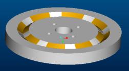
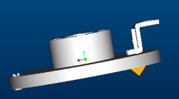
Fig. 2 Shows (a) Upper and (b) Lower Sample Selector
Assemblies.
LOWER
ASSEMBLY:
Fig.3 Sample holder
assembly and attachment to lower probe assembly.

1. Solder superconductors to current leads.
2. Thread voltage wires through stainless steel tubing.
3. Place spacers around stainless steel tubing (SS Tubing .25”
diameter).
4. Thread voltage wires through the end spacer hole.
5. Use two/three current leads to align spacer holes.
6. Epoxy spacers (2) to stainless steel tubing (voltage
wires). Allow epoxy to dry.
7. Assemble remaining leads in spacers.
8. Slide probe body (SS Tubing 2.375” diameter) over the two
spacers.
9. Thread the voltage wires through hole in the probe body.
10. Slide the probe body into place (align bottom of probe body
with bottom of the end spacer).
11. Thread sample holder connector into end spacers.
12. Bend current leads into sample holder groove profile (to
get proper shape).
13. Temporarily remove current leads from the sample holder and
braze copper pads to current leads.
14. Place current leads and sample holder together.
15. Fix copper pads to sample holder with brass screws.
16. Align bumper with sample holder and screw the blot into
lower assembly.
17. Drill two holes in the body through to the end spacer for
screws.
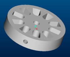
Fig.4: Current Lead Spacer
MATING
UPPER AND LOWER ASSEMBLIES:
Flange-3
![]()
![]()
1. Secure upper and lower assemblies together at flange-3 with
allen bolts.
2. Fasten the current leads to the lower connects of the
sample selector switch with screws and solder them into place.
3. Connect negative power supply to lower part of the sample
selector switch.
4. Connect positive power supply to upper part of the sample
selector switch.