1.5 Concept Generation
Function: Delaying sink
Description:
Decreasing
the rate at which the vehicle sinks will provide more time for egress for the
passengers in a sinking vehicle. The buoyancy force of this function will be
comprised of one system in place to increase the buoyancy of the vehicle and
increase the time the passengers have to escape. Four viable concepts were
generated during our ideation phase. Decreasing the rate at which the vehicle sinks is not required as part of the project scope but will prove very valuable
when giving distressed passengers a few more moments
time to escape.
Table
1: Delay sink concept generation
|
System |
Concept |
Metrics |
|
Vehicle
Insulation |
Replace
foam in vehicle with lower density foam |
Time (s) to sink a
specific depth, Acoustic (Hz), thermal
(k) properties, density (ρ) |
|
Vehicle Insulation |
Replace and add in
additional lower density foam to empty spaces in vehicle |
Time (s) to sink a
specific depth, Acoustic (Hz), thermal
(k) properties, density (ρ) |
|
Vehicle Insulation |
Vehicle
water ballast |
Time (s) to sink a
specific depth, Acoustic (Hz), thermal (k) properties, density (ρ) |
|
Vehicle Safety system |
Deploy flotation device |
Time (s) to sink a
specific depth, Time (s) to deploy
flotation device |
System: Vehicle Insulation
The insulation system is comprised of different
materials placed throughout the vehicle between the vehicle frame and interior
to provide ideal thermal and acoustic properties. Specifically, areas under the
hood, interior side, and floor panels utilize foam used to trap and reduce the
heat from the engine. The foam also acts as an acoustic damper to suppress
noise from the engine. These properties must be taken into account to ensure
our design concept does not take away from the vehicle’s original thermal and
acoustic properties.
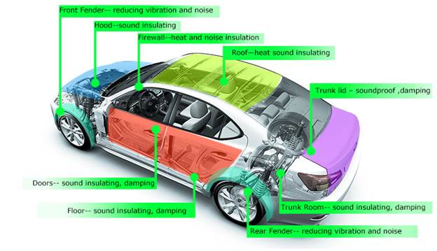
Figure 1: Vehicle
Insulation system
Concept 1: Replace existing insulation
in vehicle with lower density material
Replacing the
existing material in the vehicle with low density foam will increase the
buoyancy force therefore allowing the vehicle to sink at a slower rate. The
standard insulation material is currently used throughout the vehicle and can
be replaced in key areas such as under the hood, front and rear fender,
interior floor, side panels, and trunk. Also the replacement material must be
comparable in acoustic and thermal properties to ensure the vehicle is not
hindered from our design concept. Several materials have been researched for
use in the vehicle.
Closed cell
urethane foam has been researched as a viable low density foam option. The foam
has a density of 2 lb/ft^3 which is much less dense
than water at 62.4 lb/ft^3. It has an R-value
of 7 per inch which is comparable to other types of insulation. The foam is
mixed and molded into a desired shape to fill voids for flotation and is relatively
inexpensive. However when urethane foam absorbs water, the buoyancy force
decreases significantly.
Expanding
epoxy foam was also researched as a viable option but is much more expensive
than urethane foam. Epoxy foam does operate better at higher strength and
temperatures and is more water resistant.
Low density
egg crate shape soundproofing foam is another option in areas that thermal
insulation is not a priority, such as the trunk or cabin. The egg crate shape
foam acts as a sponge to absorb sound as most of the material is comprised of
pockets of air. The pockets of air will prove to decrease the average density
of the vehicle allowing an increase in buoyancy.
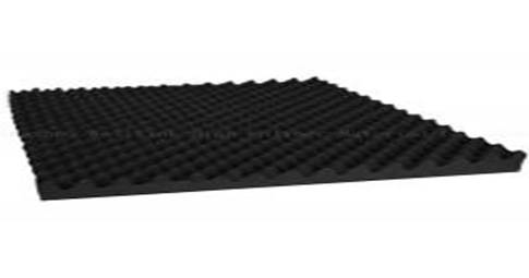
Figure 2: Low density egg crate shaped foam
Concept
2: Replace existing and add additional lower density material in vehicle
This design concept is similar to concept 1 but includes adding
additional foam to areas occupied by only air between the vehicle’s frame and
side panels. However, adding in additional foam must not hinder the car in any
ways especially thermal and acoustic properties. Additional areas aside from under the vehicle hood, and interior panels
must be investigated to ensure it will provide more buoyancy without affecting
these qualities. Similar foams will be investigated for use as discussed in
concept 1.
Soundproofing
techniques provide examples of additional areas where low density sound
proofing foam could be applied to reduce the average density of the vehicle and
further sound proofing the vehicle comparable to standard options from the Toyota
corolla.
After
discussion during our staff meeting, it was brought to our team's attention
that all areas even if only occupied by air are designed with a specific
purpose such as acoustic dampening. By adding in foam to these areas, the
dampening in the vehicle may be thrown off and hinder the original vehicle
design. Extensive investigation must be done to ensure that any areas with
newly added foam do not hinder the vehicle’s properties.
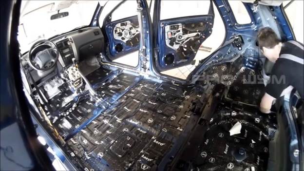 Figure 3: Cabin Interior Insulation
Concept
3: Vehicle air ballast tank
Marine
vehicles use water ballast tanks to increase stability and buoyancy. A ballast tank is a compartment within a
floating structure that holds water, which is used as ballast to provide stability
for a vessel. This
component of marine vehicles could be applied to our project but as an air
ballast tank. By sealing areas in the vehicle so water cannot occupy those
areas, the trapped air will increase the force of buoyancy and decrease the rate
of the sink. Areas that could be potentially be sealed are pockets between the
frame and interior. Other areas, such as the exhaust system, could provide more
volume for the air to be used as a ballast but could prove to be unsafe for the
vehicle if the exhaust system is accidentally sealed during normal operation.
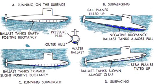
Figure 4: Water Ballast principles
System: Vehicle safety systems
The vehicle
safety systems include components such as seat belts and airbags. Airbags could
prove useful in creating buoyancy in a sinking vehicle and should be
investigated. Although no additional safety hazards, such as a
instantly deployed airbag, should be added to the system in order to abide to
our customer restraints. By adjusting the way in which the airbags are activated,
they could prove useful in delaying the rate at which the vehicle sinks.
Concept 4: Deploy flotation device
Several
components already installed in the vehicle could be used as a flotation device
to increase buoyancy of the vehicle and delay the sink. Airbags could be
inflated slowly to increase buoyancy of the vehicle by trapping pockets of low
density air but not add any potential safety hazards that usually accompany a airbag deployed at full
velocity. The airbags would continue to stay inflated in this case instead of
slowly deflating immediately after a car accident. However, each deployed air
bag would have to be replaced and could prove very costly to the operator of
the vehicle.
In addition
to the airbags, more buoyancy can be achieved by putting an inflatable
flotation device similar to an airbag in the underneath the frame of the car.
Upon the vehicle sinking, it would be deployed and inflated to increase the
buoyancy of the vehicle. This would be necessary if the buoyancy force from deploying
the airbags was not great enough to make a real impact in delaying the sink.
Function:
Sensing sinking vehicle
Description:
Sensing the vehicle condition can provide the
passengers with appropriate assistance especially in life threatening situations.
This function will be comprised of one system in place to provide the
passengers with contact with emergency first responders and signal a means to
egress the vehicle. After refining initial concepts, three viable concepts were
generated for this function. The vehicle electrical system is required to
validate our design as it will be integrated with our design concepts in order
to achieve the top priority of the project scope, saving lives in a sinking
vehicle scenario.
Table
2: Sensing sinking vehicle concept generation
|
System |
Concept |
Metrics |
|
Vehicle Electrical System |
Install a pressure
transducer underneath the body of the vehicle |
Pressure (kPa) |
|
Vehicle Electrical System |
Install a force
transducer along the vehicle suspension springs |
Force (kN) |
|
Vehicle Electrical System |
Utilize existing GPS
location device on vehicle |
Change in
elevation (m) |
System: Vehicle electrical system
Most
vehicle’s electrical systems made after fall 2009 come equipped with a variety
of sensors to help aid the driver. Such sensors include GPS location and force
transducers. The GPS location sensor is used to provide vehicle navigation.
Force transducers detect large forces which are indicative of a vehicle
accident. Toyota’s Safety Connect program utilizes the GPS location and force
transducer data to send emergency first responders to the location of the
vehicle in the event of an accident. While most new vehicles come equipped with
a variety of sensors, more can be done to detect if a large body of water is involved
during an accident.
Concept
1: Installing a pressure transducer
The pressure transducer works by converting
pressure into an analog electrical signal. This is achieved by physically
deforming strain gages that are bonded into the diaphragm of the pressure transducer
that are wired into a Wheatstone Bridge configuration.
The pressure being applied to the pressure transducer produces a deflection of
the diaphragm. The deflection or strain will produce a proportional electrical
resistance to the applied pressure. Figure 1 below shows a schematic drawing of
a standard pressure transducer.
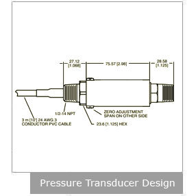
Figure 5:
Pressure transducer design from Omega.com
The electrical signal can then be used to alert
first responders that the vehicle is potentially sinking in a large body of
water. The signal could also be used as a means to begin the automatic window
drop function discussed in the assisting in egress section. The signal would be
sent to an intermediate computer that would also be connected to the window
position switch. The window would drop as normal if a signal is received that
the car is underwater a signal that the car is in water.
Installing the pressure transducer along the undercarriage is the
preferred location for this concept since most vehicles enter water in the
upright position. Figure 6 below shows the preferred location for the pressure
transducer. The concept will focus on making a meaningful impact on the number
of vehicle deaths involving water. Vehicles entering water in other
orientations will be beyond the scope of the current project but may be
addressed during future projects.
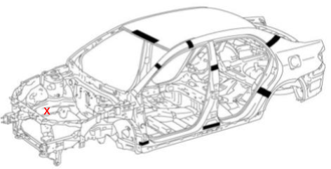
Figure 6:
Body outline of 2009 Toyota Corolla from slideshare.net indicating location of
pressure transducer.
Concept 2: Installing a force
transducer on the suspension springs
This force transducer would work with the suspension system
used in the vehicle. When a vehicle’s weight is equally distributed between
four tires on the ground and their suspensions, the springs are compressed to a
standard point. However if the same vehicle is sinking, the amount of force on
the tires from the water would be significantly less and would result in a
spring that was elongated. The force transducer would be able to detect this
difference in length by monitoring the amount of force the spring was enduring.
When the force on all four tires’ springs dipped below a calculated point and
stayed there for a given amount of time, it would be able to determine if the
vehicle is sinking.
Concept 3: Utilize
existing GPS technology
Global Positioning System (GPS) technology is
steadily advancing, particularly in the automotive industry. Toyota launched
their Safety Connect system in 2009 which has four major functions, all of
which include the use of GPS technology: Automatic Collision Notification,
Emergency Assistance Button, Roadside Assistance, and Stolen Vehicle Locator.
To make these efforts possible, GPS systems must
depend on reliable networks which include ground stations, satellites, and
receivers. There are over 30 navigation satellites hovering in space and the
ground stations use radar to reassure the overall system that the satellites
are in their “assigned” spots in space. Receivers, particularly built in
receivers in an automobile, listen for signals from the satellites. Once four
or more distances are collected by the receivers from the satellites, the
receivers then send a signal to first responders or the GUI (Graphical User
Interface i.e. built-in touchscreens on consoles) to display the location of
the car, navigate accordingly, or assist in /perform the task at hand.
By “piggybacking” off of the already existing
GPS technology and wiring, a pressure sensor can be used in conjunction with
this GPS technology in its own module to effectively and efficiently send a signal
to the Response Center so that First Responders can be alerted in a timely
manner. The latitude and longitude of a vehicle’s location is included among
the numerous data that is collected and used by Toyota. If the coordinates of
the vehicle could bypass the Response Center and go directly to First
Responders when the pressure difference of the water is first detected, this
would help reduce the response time of emergency personnel.
Concept 4: Combining Pressure Transducer and Water Detection
System
The pressure differential system uses a pressure transducer
to measure the difference in the atmospheric and water pressure which allows
the group members to set a critical pressure point signaling that the car is
sinking and not experiencing other case scenarios (i.e. heavy rains or going
through a car wash). Once the water is detected, a signal will be sent to the
egress system, in a timely manner, and passengers can begin their escape,
allowing time for all 3 passengers to get out of the car. The conjunction of
water detection and pressure differential systems can also send a more accurate
GPS location to First Responders, including depth by using the pressure
transducer’s pressure difference, in a timely manner, with the water detection
and pressure transducer working together to ensure the car is sinking as soon
as the water is detected.
Function:
Assisting in egress
Description:
Assisting the
passenger in egress is essential to increasing the survival rate in sinking
vehicle accidents. This function will focus on modifying the various exits
throughout the vehicle as well as creating a new means of egress that will make
it easier for passengers to escape while sinking. Three feasible concepts were
generated during our ideation phase. Considering that many people become
trapped inside the vehicle while it is sinking, a system designed to assist all
passengers in egress is required for our project scope to increase the chance
of saving lives.
Table
3: Assisting in egress concept generation
|
System |
Concept |
Metrics |
|
Vehicle Window Regulator
system |
Manual window dropper |
Time (s) for egress, Time
(s) to fully open window |
|
Vehicle Window Regulator
system |
Automatic window dropper |
Time (s) for egress, Time
(s) to fully open window |
|
Vehicle electrical system |
Underwater door opening
mechanism |
Time (s) for egress, Time
(s) to fully open door, Force (kN) to open door
while vehicle is submerged |
System: Automatic Window Regulator
System
Most cars
manufactured in the past 10 years are equip with power window regulators used
to open and close the window using a button. The automatic window regulator
system is used throughout the vehicle and allows the passengers to open or
close the windows with a push of the button as opposed to physically cranking
the window. Our concepts would allow for the window to drop to allow for the
passengers’ egress but would not affect the window regulator system’s current
function.
The first
design concept question was how the passenger should exit. One option was for
the system to break the windows. However, one of the project constraints was to
not add any potential hazards such as broken glass to the situation. Thus,
focusing on the window regulating system will provide an opportunity to open a
window for the passenger quickly and safely.
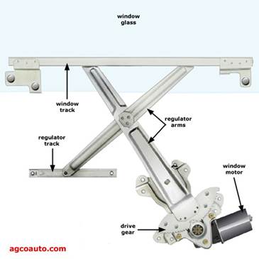
Figure 7: Vehicle Window Regulator system
Concept 1: Manual Window Dropper
The manual
window dropper will function using a lever near the bottom corner of the driver
side window that will drop the driver side front window. This design concept
would not be a part of the vehicle’s system that included the sensor as it
relies on the passenger to engage. This could be useful in the event that the
electrical system fails due to impact or water damage but the system would rely
on a distressed vehicle operator to have to activate the lever quickly in order
to survive. Once the manual window dropper is activated a signal would be sent
to first responders similar to Toyota's safety connect.
Precautions
must be taken to ensure the window will still drop even if the water level has
risen to the height of the window. As the water level increases in height on
the window pressure forces will continue to rise, risking failure in the
dropper mechanism and failing to drop the window for the sinking passengers.
Concept 2: Automatic Window Opener
This concept
would work with the window regulator system and would automatically drop the
window. The window dropper would be integrated with the sensing system that
would be able to detect the vehicle sinking. This system would include the
sensor as previously mentioned that would signal the window dropper to activate
automatically in the event that the vehicle is sinking..
By automatically dropping the window, the passenger would have a means to
escape the vehicle without having any direct interaction with the window
itself.
During the
first minute of the sink, the passengers in the vehicle have the highest chance
of survival as the water level will not at the top of the window. Once the
water level is near the top of the window, pressure forces are exerted against
the window and could prevent it from being dropped. To ensure this is not the
case, the automatic window dropper must drop the window at full velocity within
0.5 seconds of the sensor sensing that the vehicle is sinking.
Special
precautions must be taken to ensure the automatic window dropper does not
accidentally activate due to a splash of water or hitting a speed bump.
Concept 3: Underwater Door Opening
mechanism
An underwater
door opener concept would be integrated into the electrical systems of the
vehicle so that enough power could be produced to force open the door while the
vehicle is sinking. This mechanism would assist the passengers in opening the
door despite the growing force of the water pressure on the outside of the door
as the vehicle is sinking. The opener would be placed within the door frame and
as the sensors detect the sink of the vehicle, this mechanism would begin to
expand. As it expands, the door would open and create a means of escape.
It becomes
increasingly more difficult for the door of a car to open as a car sinks. This
means that the car door must be opened almost instantly upon impact with the
water. The automatic door opening system must be activated the instant that the
sensor network senses that the car is in water, and it must open the door in
less than 4 seconds to ensure that the passengers can escape. The door opener
must work very quickly because if the door is open it allows much more water to
enter the cabin of the vehicle than if only a window is open, causing the
passengers to have less time to escape from the vehicle before it fills
completely with water.
Precautions
must be taken to ensure that the automatic door opener can withstand the force
of water outside of the vehicle even after the water reaches the top of the
door. As previously stated, as the water level rises the amount of force needed
to open the car door also rises.
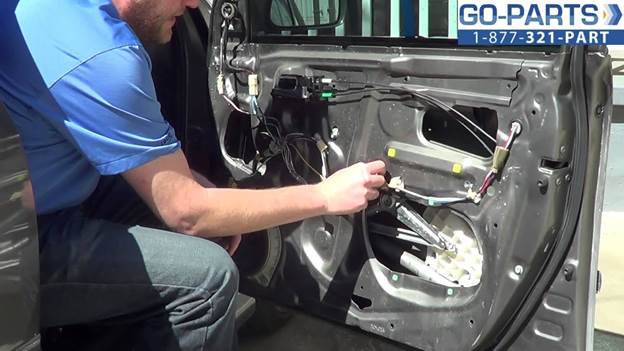 Figure 6: Installed Window Regulator