Design of Concept
 Working Enviroment
 Material Selection
 Thermal Analysis
 Components
 Enginering Drawings

Working Enviroment
A resistive magnet will be used to produce a variable magnetic field
in which to grow the yeast. With this constraint, a better understanding of
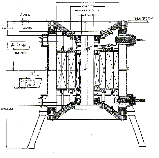
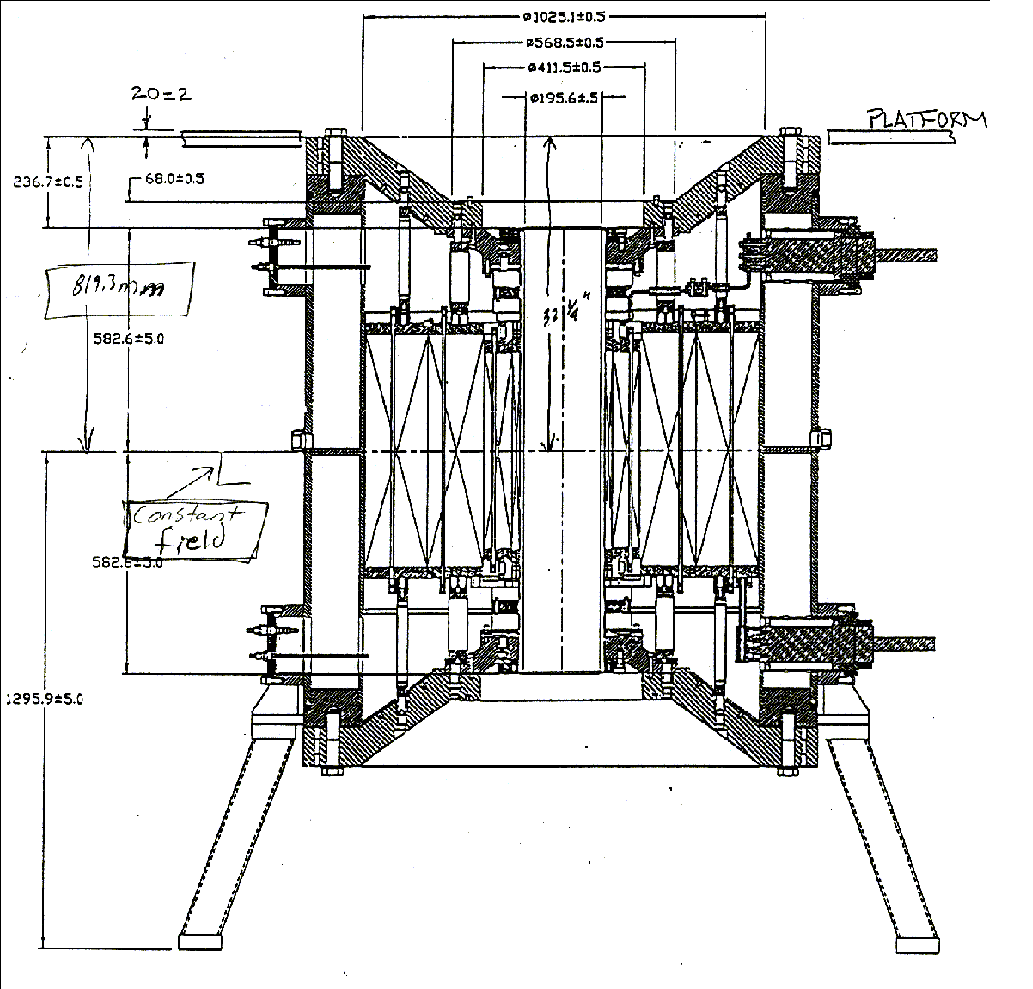
the magnet was necessary. Below is the schematic for the magnet that will be
used in this experiment. The maximum magnetic field strength of this
magnet is 20 tesla. The axial location of the center of this field is 81.93
cm below the top of the magnet and it remains constant for approximately 3.00
cm above and below the center point. The radial field decreases exponentially
with respect to the distance away from the axis of the bore. The operating
temperature inside the bore of the magnet is approximately 8 degrees Celsius
and the diameter of the bore is 19.56 cm. The magnet is stored in cell #4 at
the National High Magnetic Field Laboratory (NHMFL) in Tallahassee, Florida.
 Resistive Magnet/Working Enviroment
 Click here for a larger view.
Back to top

Material Selection
A vital decision in our design process involved the selection of the
proper materials. Selecting the material for the shell
casings and the tubing of the device included several constraints due to
the working environment. The casings required a material with particular
properties such as: nonmagnetic, low density, high ultimate tensile strength,
low cost and low thermal conductivity. The three possibile materials chosen
for this application were stainless steel, aluminum, and copper. In determining
the inner tubing, many attributes were taken into consideration. The
primary concern was preventing oxidation of the tubing and contamination
to the medium. From the table below aluminum was chosen to be the most practical for
the shells. Stainless steel was chosen for the oxygen inlet tube
because of its high corrosion resistance. The external water tubing
requirements consisted of flexibility, low cost and high thermal
resistivity. The tubing selected for this application was a polymer
material (garden hose), which will be easily obtained from any hardware
store. The growth container, which sits inside the inner casing, requires
Spectrosil grade silica (transparent) and an optically flat base.
The size of the container must not exceed 4-cm diameter with maximum
durability. From these constraints a beaker made from Pyrex was
chosen to be most suitable. This concludes the material selection
portion of the design of concept.
 Material Properties
Back to top

Thermal Analysis
Final Calculations
Intial Calculations
Back to top

Components
Components were researched individually and chosen depending on the design
constraints. A critical obstacle in selecting the components was adjusting
theoretical component parameters to the existing manufacturer specifications.
Extensive research and analysis produced the most feasible solution for each
element of the design. Below is a list of selected components and the reasoning
behind their selection.
Shell Casings:
Initially the design incorporated a quadruple aluminum casing. The
two outer and inner casings were filled with insulation, which allowed a
space between the two to create a water jacket. The dimensions of the
shells were optimized using the thermal and bore constraints. However the
casings with the determined dimensions are not commonly manufactured. This
led to modifications in shell dimensions. The new dimensions of the design
were based upon availability of the shell casing and the revised thermal calculations.
See thermal calculations in Appendix D, E and engineering drawings in
Appendix G.
Pump:
Thermal calculations were preformed with various mass flow rates in order
to determine the one most efficient for the system. Results from the
calculations proved the desired mass flow rate to be 400 gph. Three companies
that manufactured a pump, which met this requirement, were Pondmaster, Rena,
and Aqua Master. From these Pondmaster provided the simplest, cheapest pump
with a five-year warranty. This pump has a half-inch diameter inlet and
outlet and costs around $80.
Insulation:
Constraining factors for choosing the insulation were the workability and R value.
There were four reasonable types, which includes a fiberglass blanket, loose
fill fiberglass, perlite and the spray polyurethane foam. Due to the greatest
R value and the easy method of application, the spray Polyurethane foam was
preferred. The manufacturer of this foam is "Great Stuff" and costs $3.75
a can at the local hardware store. The approximate amount of cans required
is 5.
Beaker:
The beaker, which sits inside the inner casing, requires Spectrosil grade silica
(transparent) and an optically flat base without producing contamination to the
yeast medium. The size of the container must not exceed 4-cm diameter and must
also provide durability. From these constraints a beaker made from Pyrex was
chosen to be most suitable.
Thermocouple:
Two models were examined for the design's environmental temperature measuring
device. The thermister and thermocouple, which provide basically the same
function, was researched to decide the most feasible unit for the design.
Through observation of the two models, the primary factor in this decision
was cost. The Iron-Constantan thermocouple, manufactured by Scientific
Instrument Inc., had the lowest cost and also provided the ability to measure
temperatures to 800 degrees C. The main difference between the thermocouples
was the wire diameter. The smaller the diameter of the wire the faster
primarily an equilibrium temperature condition, a thermocouple with a wire
diameter of .005 in. was chosen for the design.
Data Recording System:
An approach to acquire system data was necessary for performing the yeast
experiment. The sponsor proposed two systems for data acquisition, manual
and automatic. The manual method is the least desired because of an abundance
of equipment, constant supervision and less accuracy. For these reasons
the automatic method was selected for the data recording system. Lab View
is the desired software for this function because of its accessibility and
help benefits from experienced personal. This method is more complicated
to set up however once implemented the experiment will run much smoother,
the error associated with the experiment will be significantly decreased,
and the operation of the experiment will become more convenient.
Photon Multiplier (PM tube):
A PM tube is required to perform this experiment as a way of measuring
luminescence emission produced by the yeast. The selected PM tube must
have high cathode sensitivity near 75 micro amps and low dark current
close to 0.5 nano amps. Other requirements include magnetic shielding and
a sensitivity wavelength between 200-630 nano meters.
Fiber Optics:
Constraints discussed previously directed the design to incorporate fiber
optics as a tool for transporting the light from the yeast medium to the
PM tube. The optic cable must be reasonably flexible for ensured
perseverance under stressful situations, be fairly priced and be shielded
from outside interference. In deciding the length of the cable the distribution
of the magnetic field was taken into account. This was accounted for because
the PM tube can only operate correctly under a magnetic field less than
20 gauss. Running the experiment with a 20 tesla field will require the
PM tube to be at least four meters away from the magnet. From Appendix
F the required distance from the magnet can be extrapolated.
Back to top

Engineering Drawings
The purpose of generating the engineering drawings was to insure the feasibility
of the system and provide help to the machinist in developing the components.
By producing the drawings it will also give a better visual conceptualization
of the system design. The drawings were created using ProE.
Click here to see the System Drawings
Back to top


Last Revised: 2000-12-20
 Resistive Magnet/Working Enviroment
![]()
 Material Properties
![]()
![]()
![]()
![]()
