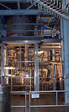
Image of the 45 Tesla Hybrid Magnet at the National High Magnetic Field
Lab (NHMFL). The magnet system weighs 34 Tons although our column
will only be required to support 12 Tons directly (without any magnetic
load).
Purpose
Image of the 45 Tesla Hybrid Magnet at the National High Magnetic Field
Lab (NHMFL). The magnet system weighs 34 Tons although our column
will only be required to support 12 Tons directly (without any magnetic
load).
Purpose
The purpose of our project is fundamentally stated in the project description presented on the main page. Our goal is to design a support column which is optimized for thermal efficiency, build a smaller scale model, and test that scale model against our original theoretical models.
The purpose of this section is to more clearly illustrate the design
process employed for the completion of this project.
Semester 1 (Fall 99):
Complete a finalized design for a support column which is optimized
for thermal efficiency.
Semester 2 (Spring 00):
1) Modify the design for the support column to conform
to a smaller test apparatus, and build the modified column.
2) Test the model column for both structural stability
and thermal performance/efficiency.
The process for producing a finalized design for a support column was threefold. Our first step was to analyze the current system and create comparisons against ideal system. This was achieved through producing mathcad and excel files simulating temperature profiles and by determining the specifications our mentor required. Our second step was to produce a numerical solution for the column which allowed for the optimization of both material and refrigeration power for the column. This step is detailed in our numerical solution (on paper). Our final step is to produce and test a smaller scale model. This step was scheduled to be realized this semester (Spring 00), and is discussed in detail on the second design page.
Ideal/Theoretical Models and Project Specifications
Ideal Temperature Profiles
Numerical Solution (Our Solving Process)
Design Process
Mentor's Solution
Because our method for solving the system could not be completed, our mentor provided a spreadsheet with his calculations. This set of calculations was a less strenuous approach to solving the system and included assumptions for the temperature of the fluids and had detailed values for the material properties of helium and steel.
The primary values that were input into the sheet were the initial fluid temperature and the initial rise in temperature for the fluid. The values that were extracted from the spreadsheet were the optimal location for the intake manifold and the overall cooling fluid usage rate.
The schedule shown in the accompanying set of tables is the optimized design for the 100mm intake manifold location. It indicates a fluid usage of 2.6 L/h for a 4.75K rise in initial temperature. The usage at those conditions is approximately .2 L/h greater than the absolute minimum usage which was found to be approximately 2.4 L/h. This is an acceptable increase in required cooling power because it allows the system to be more efficient if a larger increase in initial temperature occurs in our system.
In order to better demonstrate our processes (and problems) we have included our final presentation and final design document to aid with the explanation of our project. Many of the issues included in these documents are discussed within this website, however, the presentation and design paper provide a more concise view of the first 4 months of work done on this project.
Final Design Paper (Fall 99)
Note: The Design Document is exerpted throughout the website.
Some of the topics included in certain areas of the site are directly taken
from this document.